RF Power Systems · Seville, Spain
RF Power Processing Units for Plasma Thrusters
Software-defined, GaN, with adaptive impedance matching. 50 to 500 W at 13.56 MHz.
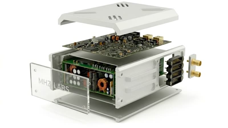
We build the RF power processing unit and adaptive impedance matching network for RF and helicon plasma thrusters, as a standalone subsystem for the propulsion manufacturer. The thruster produces thrust. The RF PPU decides when, how much, and how, and holds the match while the plasma moves.
How We Think About
the RF Power Chain
Our point of view, shaped by conversations with thruster teams and the public literature. It will not match every programme.
A helicon or RF plasma source is a time-varying electrical load: its impedance can move by an order of magnitude from cold gas to full plasma, and again with operating point. Teams handle it with an oversized generator, a hand-tuned bench match, or a mix. What they share is that the hardware that works in a vacuum chamber is not the hardware that flies, and closing that gap is real engineering that often has no clear owner. We think it is worth building as a product.
What the RF chain can cost, one published case: in a 1 kW helicon programme (UC3M and SENER, 2015 to 2019), an early campaign measured propellant utilisation at or below 1 percent, most of the RF power lost in the feeder and matching network before the antenna. A revised setup recovered it to around 19 percent at 900 W, a swing the authors put down to the RF chain alone.
New to RF PPUs? Start with the technical guide.
What We Build
RF PPU · Adaptive matching network · RF generator module
01 · RF PPU
The RF power processing unit
Spacecraft bus power to matched RF drive, 50 to 500 W, with fast VSWR protection and no circulator on the mass budget.
Specification and architecture02 · AIMN
Adaptive impedance matching
Closed-loop matching that tracks the plasma in real time, so the amplifier is never oversized to absorb the mismatch.
How it works03 · RF Generator
The RF generator, as a module
The ionisation stage on its own, with a documented power-setpoint and telemetry interface, for teams that keep the rest in-house.
The building blockDesign Targets
Engineering model targets. Nothing here is flight-qualified yet.
| RF output power | 50 to 500 W |
|---|---|
| Operating frequency | 13.56 MHz for helicon sources; lower for RIT-class thrusters |
| DC input | Two redundant 28 V DC inputs (standard spacecraft bus), design range 18 to 40 VDC |
| Power stage | GaN, switch-mode |
| Power control | Software-set, about 10:1 range, no mechanical tuning |
| Load tolerance | VSWR ride-through without a circulator or isolator |
| RF output | 50 ohm coaxial; antenna match or adaptive network as a separate downstream module |
| Command and telemetry | Spacecraft data bus, autonomous fault handling |
| Thermal | Conduction to a baseplate or cold plate |
| Mass | Product target under 2 kg |
| Supply chain | COTS-first, European, ITAR-free |
DC-to-RF efficiency is not published while it is unmeasured. It will be added here once we have a figure from the bench. Full specification and architecture →
Design Partners,
Early
We are opening one or two design-partner slots with propulsion OEMs, to define the PPU interface against a real thruster while the requirements are still cheap to change. Further along on the thruster and want the power chain handled? That is the conversation we want. A first call implies no commitment either way.
Two tools already run behind the design: the COTS Heritage Database for space-qualified RF and power parts, and an internal simulator for the matching network and its control.
Get in touch
Building an RF or
Helicon Thruster?
We would like to hear how you build and tune the RF power chain today and where it costs you schedule, whether that becomes a build-versus-buy conversation or just a chance to compare notes on a hard problem. We are not asking for proprietary specifications.